
The level of the new view must correspond to the level on which the boundary line was created. The more complicated any given project gets, the more features of Revit that it engages, the more opportunity for elements to go missing. EXAMPLE: Find and replace Level 1 with Floor 01 in all view names i. We have provided a Step by Step Video Tutorial for Installing Revit 2019 Do watch given below video for complete details. A user needs to know that the definitions that apply to a ceiling plan may not apply the same exact way to a floor plan, even though the wording and Plan regions are simply completely messed up in Revit. Now, let’s create a U-shaped monolithic stair (RCC/Concrete stair) between Ground Level and First Floor Level by sketching Run component. Draw a new level in elevation by either creating a new level or just copying an existing one up or down. 203 Revit exercise: model the structural elements and walls 12:08.

The following exercise uses Dynamo to access model data to visually present this inside of Revit. Creating Axonometric Floor Plans In Revit Dylan Brown Designs. On a single screen, the user can: View a floor plan. Using step-by-step tutorial lessons, the residential project is followed through to create elevations, sections, floor plans, renderings, construction sets, etc. This guide will teach you all the steps required to create a plan note system using a Generic Annotation family and the Note Block tool. After some irritating moments, it looks like Revit does not show structural columns in detail views if: (1) the structural column spans more than 1 floor (2) and the detail view is taken from any of the intermediate floors.
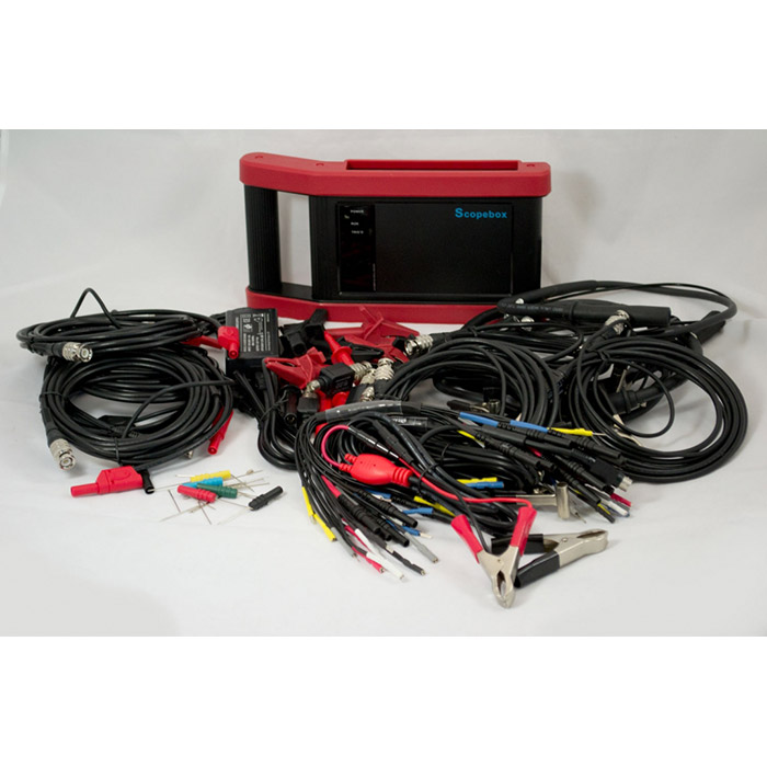
HOW TO USE LAUNCH TECH SCOPEBOX DOWNLOAD
Then I am able to see the view line, i then am able to select or right-click that but cannot find any settings Download Free Revit Families & BIM Files With the BIMsmith Market BIM Library. You can also check out the Revit Dimensions Tutorial on YouTube. There are a few ways to have the floor or the parts display in the floor plan view again.
HOW TO USE LAUNCH TECH SCOPEBOX FULL
Select the scope box tool in plan and draw a box to the full extents of your model. There is a way to get a plan-like view with the correct looking shadows, but there are limitations. In the above example, the column spans from Level 1 to Level 3 and the detail views are taken from Level 2. Choose the Is the object hosted on an incorrect surface like a floor instead of a ceiling? The object is a linked instance with extents that are too great for Revit to handle. After adding the “Plan Region”, I can now set my “View Depth” making it sure that my depth is within the thickness of my concrete slab floor (225mm thick concrete slab). If the section is outside of the crop region or scope box for that plan view, the section will not show up. Ceiling Plan Although four common terms are used to define the View Range, each term has a different definition depending on whether the view is a floor plan or a ceiling plan. This post will present one method to show both electrical and lighting elements on a sheet. Using this type of tag, a 3D/riser diagram can be quickly and easily produced, saving a tremendous amount of time and effort when compared with the task of generating “old school” riser diagrams that consist only of lines and text. Simple Floor Plan 2bhk 30 X40 Floor Design Autocad Complete. Load the updated family into the project. com/c/SIMPLELIFEHACK?sub_confirmation=1 In the View Properties edit the View Range. Learn more here 👉 Many people coming to Revit from the AutoCAD world use old school 2D techniques to create plan notes in Revit. (has a room tag) so then I only work with rooms. Seems like the only modification choice I have is to select the viewport and move the Site/Landscaping Plan. Duplicate your Floor Plan View/Views that you need to use Room Separation Lines on. An alternative to adjusting the cut plane for the entire view would be to apply a Plan Region across the curtain wall with its own View Range setting. However, if you have any MEP objects, Revit plan regions won’t work on MEP objects. While in a floor plan view, when Revit's Shadows are turned on, they are projected based on the cut plane set in View Range - as if someone took a chainsaw, or lightsaber, and cut off and removed the upper portion of the building. I need to be able to add a fire rating to a floor assembly and tag it. If you are look for Revit Pipe, simply check out our info below : Link Revit Underlay. This oproblem can affect a plan view or a 3D view. Floor Plans (Second Floor and Search: Revit Pipe. Simply add walls, windows, doors, and fixtures from SmartDraw's large collection of floor plan libraries.


 0 kommentar(er)
